Modern factories, data centers, and medical systems depend on signals that cannot tolerate random electrical noise. Variable-frequency drives, motors, wireless transmitters, and dense power systems can create electromagnetic interference (EMI). A damaged waveform may appear as a small flicker on an oscilloscope, yet it can trigger a false sensor alarm or corrupt a control command. Shielded Cable helps reduce this risk by surrounding conductors with conductive foil, braid, or both.
The International Electrotechnical Commission’s IEC 61000-5-2 guidance emphasizes proper cable shielding and bonding within electromagnetic environments. Its recommendations show that shielding performance depends on installation quality, not cable selection alone. The IEEE 802.3 standards also recognize cabling performance as essential for reliable high-speed Ethernet and power delivery. Meanwhile, the Uptime Institute’s Global Data Center Survey continues to document costly service interruptions, reminding engineers that small physical weaknesses can create large operational consequences. These reports do not prove that every application requires Shielded Cable. That would be an oversimplification.
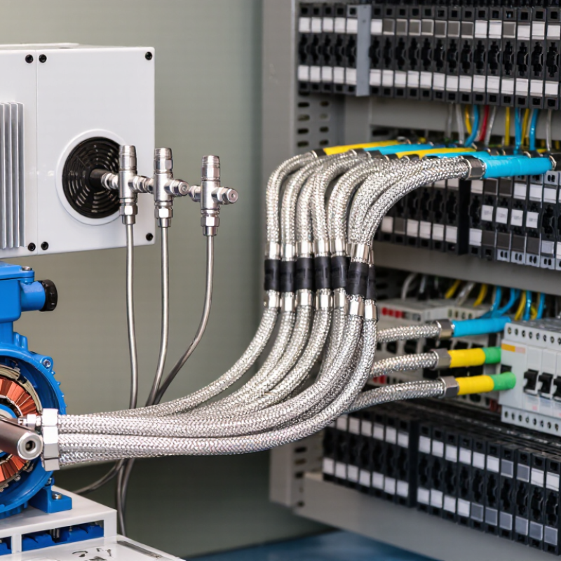
The practical advantage becomes clear near a motor cabinet. A correctly terminated shield can limit noise entering the signal pair, protecting stable readings from pressure, temperature, or position sensors. However, poor grounding may reduce performance or create unwanted ground-current paths. Cable routing, connector design, bend radius, and termination quality still matter. No cable is perfect.
This article explains when Shielded Cable provides measurable value, how different shielding designs behave, and which installation details deserve closer inspection. The goal is not to sell extra metal. It is to build a signal path that remains dependable when the surrounding equipment becomes electrically noisy.
What Shielded Cable Is and How It Protects Signal Integrity
Shielded cable is a cable with a conductive layer around its signal-carrying wires. The layer may use foil, braided metal, or both. It surrounds the inner conductors beneath the outer jacket. A shield is not a magic wall. It needs proper grounding and careful installation to work well.
In a factory test area, nearby motors can create electromagnetic interference that distorts low-level sensor signals. The shield intercepts much of this unwanted energy and directs it toward ground. This helps preserve the signal’s original voltage, timing, and waveform. The result can be fewer false readings, unstable data, and communication errors. Short connections still matter. Excess cable length can act like an antenna.
The shield must remain continuous through connectors and junctions. Damaged foil or loose braid can weaken protection at the exact point where interference enters. Grounding both ends may improve high-frequency protection, but it can create ground-loop noise in some low-frequency systems. Grounding one end may reduce that noise, though it is not always the strongest choice. I have seen installers blame the cable when poor termination caused the failure. Cable selection, routing, bend radius, and equipment grounding deserve equal attention. Reliable protection comes from the complete signal path, not the shield alone.
Common Sources of Electrical Interference in Cable Systems
Why Use Shielded Cable for Reliable Signal Protection?
Common Sources of Electrical Interference in Cable Systems
In working environments, electrical interference often begins with nearby power equipment. Motors, variable-speed drives, and switching power supplies can create changing magnetic and electric fields. These fields may enter unshielded signal cables and distort low-level measurements. A sensor reading can then jump, drift, or appear unusually noisy. I have seen this happen when a communication cable ran beside a motor feeder for several meters. The cable itself was healthy. Its route was not.
Shorter distances help.
Relay coils and fluorescent lighting can also produce sharp transients. Radio transmitters may introduce unwanted high-frequency energy. Cables installed close together can suffer from crosstalk, especially when one carries fast digital pulses. Ground potential differences create another problem. They can drive circulating currents through cable shields or signal references. Poor cabinet layout makes these effects worse.
Shielding provides a conductive barrier around the signal pair. When correctly grounded, it redirects much of the external noise away from the conductors. The grounding method depends on frequency, equipment design, and local wiring conditions. Connecting a shield at both ends may improve high-frequency protection, but it can also create ground-loop problems in some systems. This detail is often overlooked. Shielded cable is not a cure for careless installation. Separation from power wiring, proper termination, and thoughtful grounding still matter. In difficult sites, measuring noise at the installation is more reliable than guessing from a cable specification.
How Shielding Materials and Designs Reduce Signal Noise
Shielding does more than wrap a cable in metal. In practice, it creates a controlled path for unwanted electromagnetic energy. A braided copper shield offers broad coverage and low resistance. Foil shields provide nearly complete coverage. However, foil can be mechanically fragile. That trade-off matters. Industry testing makes the difference measurable. IEC 62153-4-4 uses transfer impedance to assess shield performance across frequency. Lower transfer impedance generally means less coupled noise. Designers should check the tested frequency range, not only the coverage percentage.
Grounding and termination often decide whether shielding works. A 360-degree clamp termination usually performs better than a long drain-wire pigtail. Long pigtails add inductance, especially as frequency rises. IEC 61000-4-6 evaluates conducted immunity from 150 kHz to 80 MHz. That range reflects industrial concerns, including variable-speed drives and switching power supplies. In field troubleshooting, noise often appears when a shield connects at one end only. That is not always wrong; low-frequency ground-loop conditions can change the choice. Installation geometry remains easy to underestimate. A cable beside a motor lead may need stronger separation, not thicker shielding. Standards help, but measurements should confirm the decision. Oscilloscope probes and spectrum analyzers reveal weaknesses. I have seen excellent cable designs fail at connectors.
Key Benefits of Shielded Cable in Different Applications
Why Use Shielded Cable for Reliable Signal Protection?
Key Benefits of Shielded Cable in Different Applications
Shielded cable earns its value where electrical noise can distort a useful signal. Its conductive layer helps reduce interference from motors, relays, power lines, and radio equipment. In factory sensor circuits, this protection can preserve accurate readings across long cable runs. A stable waveform matters.
Field technicians often inspect cable routing before blaming a device. A shield placed beside a high-current cable may still collect unwanted noise. Correct grounding and proper termination are equally important. Shielding is not magic. A poorly connected shield can create another problem.
In audio systems, shielded cable helps limit hum near amplifiers, lighting controls, and power supplies. In medical monitoring equipment, cleaner signal transmission supports clearer readings from delicate sensors. Industrial control panels also benefit when analog signals travel near switching equipment. Data communication systems may use shielding to reduce electromagnetic interference and maintain consistent performance.
Engineers usually select the cable after checking frequency, distance, flexibility, and grounding conditions. Braided shields offer strong coverage and mechanical durability. Foil shields can provide effective high-frequency protection in compact installations. Each design has trade-offs. Extra shielding may increase stiffness, diameter, and installation cost.
I have seen installations fail because the cable was suitable, but the connector was not. That detail deserves more attention. Testing should include real operating conditions, not only a quiet workshop. Measure noise at the sensor, inspect termination points, and check whether nearby equipment changes the signal. A reliable cable system depends on all of these small decisions.
Factors to Consider When Selecting and Installing Shielded Cable
Selecting shielded cable begins with the environment, not the connector. Measure motor drives, welding equipment, radio transmitters, and long parallel power routes near the cable path. These sources can introduce electromagnetic interference. ISO/IEC 11801-1 defines a 100-meter channel model for balanced copper cabling, including patch connections. That distance remains practical only when attenuation, crosstalk, and installation quality stay within limits. A higher category is not automatically safer.
Choose the shield type carefully. Foil shielding offers broad coverage, while braid shielding provides stronger mechanical protection and lower resistance. Some cables combine both. Check operating frequency, conductor size, temperature rating, bend radius, and required data rate. For powered Ethernet, IEEE 802.3bt permits up to 90 watts from the power source under Type 4 conditions. That load increases heating concerns inside crowded pathways. Cable bundles need realistic derating.
Installation errors are common. I have seen excellent cable fail because its shield was trimmed too far from the connector. Use compatible shielded plugs, maintain full shield continuity, and bond equipment correctly. ANSI/TIA-568.2-D also emphasizes separation from power wiring and controlled termination practices. Avoid sharp bends and crushed sections. Keep the route tidy.
Grounding deserves caution. One poorly planned connection can create unwanted current paths or noise. Follow the facility’s earthing design and applicable IEC 61000-5-2 guidance. Test insertion loss, wire map, shielding continuity, and alien crosstalk after installation. A perfect shield cannot rescue careless workmanship. I still recheck crowded panels, because assumptions fail there.
Why Use Shielded Cable for Reliable Signal Protection?
Shielded cable helps reduce electromagnetic interference by surrounding the signal conductors with a conductive layer. The chart compares representative nominal shield coverage for common cable constructions.
Foil shields can provide nearly continuous coverage, while braided shields offer mechanical strength and lower-frequency shielding performance. Actual protection also depends on cable construction, connector termination, grounding, cable length, frequency, and installation practices. Representative coverage values: unshielded 0%, braid approximately 70–95%, foil approximately 100%, and foil plus braid approximately 100%.
FAQS
A shielded cable has a conductive layer around its signal-carrying wires. The shield may use foil, braided metal, or both. It sits beneath the outer jacket. It is not a magic wall.
The shield intercepts unwanted electromagnetic energy near the cable. It directs much of that energy toward ground. This can preserve voltage, timing, and waveform. Errors may still happen.
Motors, switching power supplies, and motor leads can produce interference. A cable routed beside a motor lead may collect noise. Greater separation may help more than thicker shielding. Short connections matter.
Foil provides nearly complete coverage around the conductors. However, foil can tear or weaken during repeated movement. A braided metal shield offers broad coverage and low resistance. The choice depends on frequency and mechanical conditions.
Grounding both ends can improve high-frequency protection. However, it may create ground-loop noise in some low-frequency systems. Grounding one end may reduce that noise. There is no universal answer.
The shield should remain continuous through connectors and junctions. Damaged foil or a loose braid creates an entry point for interference. A 360-degree termination usually performs better than a long drain-wire pigtail. Pigtails add inductance.
Yes. Excess cable length can act like an antenna. It may collect more electromagnetic energy from nearby equipment. Keep connections reasonably short and avoid unnecessary loops. This detail is easy to miss.
Oscilloscope probes can reveal unstable waveforms and unexpected noise. Spectrum analyzers can show interference across different frequencies. Measurements should confirm installation decisions. I would not blame the cable too quickly.
Conclusion
Shielded Cable is designed to protect electrical signals from interference that can reduce performance, cause data errors, or create unwanted noise. Its conductive shielding layer surrounds the signal-carrying wires and helps block electromagnetic and radio-frequency interference from sources such as motors, power lines, wireless equipment, and nearby cables. Depending on the application, shielding may use foil, braided metal, or a combination of materials to improve coverage and flexibility.
The main benefits of Shielded Cable include stronger signal integrity, improved reliability, reduced crosstalk, and more stable operation in industrial, commercial, communication, and sensitive electronic systems. When selecting a cable, users should consider the required signal type, frequency range, operating environment, flexibility, grounding method, and level of interference. Proper installation is equally important: the shield should be terminated correctly, routing should minimize exposure to noise sources, and bends or mechanical stress should remain within the cable’s limits.

 Laurence